A 320 Technician ][ .. مشرف قسم .. ][ ][ هندسة وصيانة الطائرات ][
Aircraft Propellers - iii **Control and Operation**
AIRCRAFT PROPELLER CONTROL AND OPERATION
Propeller Control
basic requirement: For flight operation, an engine is demanded to deliver power within a relatively narrow band of operating rotation speeds. During flight, the speed-sensitive governor of the propeller automatically controls the blade angle as required to maintain a constant r.p.m. of the engine.
Three factors tend to vary the r.p.m. of the engine during operation. These factors are power, airspeed, and air density. If the r.p.m. is to maintain constant, the blade angle must vary directly with power, directly with airspeed, and inversely with air density. The speed-sensitive governor provides the means by which the propeller can adjust itself automatically to varying power and flight conditions while converting the power to thrust.
Fundamental Forces : Three fundamental forces are used to control blade angle . These forces are:
1. Centrifugal twisting moment, centrifugal force acting on a rotating blade which tends at all times to move the blade into low pitch.
2. Oil at engine pressure on the outboard piston side, which supplements the centrifugal twisting moment toward low pitch.
3. Propeller Governor oil on the inboard piston side, which balances the first two forces and move the blades toward high pitch
Counterweight assembly (this is only for counterweight propeller) which attached to the blades , the centrifugal forces of the counterweight will move the blades to high pitch setting
Constant Speed, Counterweight Propellers
The Counterweight type propeller may be used to operate either as a controllable or constant speed propeller. The hydraulic counterweight propeller consists of a hub assembly, blade assembly, cylinder assembly, and counterweight assembly. The counterweight assembly on the propeller is attached to the blades and moves with them. The centrifugal forces obtained from rotating counterweights move the blades to high angle setting. The centrifugal force of the counterweight assembly is depended on the rotational speed of the propellers r.p.m. The propeller blades have a definite range of angular motion by an adjusting for high and low angle on the counterweight brackets. Controllable : the operator will select either low blade angle or high blade angle by two-way valve which permits engine oil to flow into or drain from the propeller
Constant Speed : If an engine driven governor is used, the propeller will operate as a constant speed. The propeller and engine speed will be maintained constant at any r.p.m. setting within the operating range of the propeller
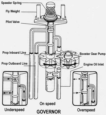
Governor Operation (Constant speed with counterweight ) the Governor supplies and controls the flow of oil to and from the propeller. The engine driven governor receives oil from the engine lubricating system and boost its pressure to that required to operate the pitch-changing mechanism. It consists essentially of :
1. A gear pump to increase the pressure of the engine oil to the pressure required for propeller operation.
2. A relief valve system which regulates the operating pressure in the governor.
3. A pilot valve actuated by flyweights which control the flow of oil through the governor
4. The speeder spring provides a mean by which the initial load on the pilot valve can be changed through the rack and pulley arrangement which controlled by pilot.
The governor maintains the required balance between all three control forces by metering to, or drain from, the inboard side of the propeller piston to maintain the propeller blade angle for constant speed operation.
The governor operates by means of flyweights which control the position of a pilot valve. When the propeller r.p.m. is below that for which the governor is set through the speeder spring by pilot , the governor flyweight move inward due to less centrifugal force act on flyweight than compression of speeder spring. If the propeller r.p.m. is higher than setting , the flyweight will move outward due to flyweight has more centrifugal force than compression of speeder spring . During the flyweight moving inward or outward , the pilot valve will move and directs engine oil pressure to the propeller cylinder through the engine propeller shaft
Principles of Operation (Constant Speed with Counterweight Propellers)
The changes in the blades angle of a typical constant speed with counterweight propellers are accomplished by the action of two forces, one is hydraulic and the other is mechanical.
1. The cylinder is moved by oil flowing into it and opposed by centrifugal force of counterweight. This action moves the counterweight and the blades to rotate toward the low angle positon.
2. When the oil allowed to drain from the cylinder , the centrifugal force of counterweights take effect and the blades are turned toward the high angle position.
3. The constant speed control of the propeller is an engine driven governor of the flyweight type
Governor Operation Condition
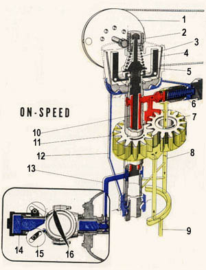
On-Speed Condition
The on-speed condition exists when the propeller operation speed are constant . In this condition, the force of the flyweight (5) at the governor just balances the speeder spring (3) force on the pilot valve (10) and shutoff completely the line (13) connecting to the propeller , thus preventing the flow of oil to or from the propeller
The pressure oil from the pump is relieved through the relief valve (6). Because the propeller counterweight (15) force toward high pitch is balanced by the oil force from cylinder (14) is prevented from moving, and the propeller does not chang pitch
Under-Speed Condition
The under-speed condition is the result of change in engine r.p.m. or propeller r.p.m.which the r.p.m. is tend to lower than setting or governor control movement toward a high r.p.m. Since the force of the flyweight (5) is less than the speeder spring (3) force , the pilot valve (10) is forced down. Oil from the booster pump flows through the line (13) to the propeller. This forces the cylinder (14) move outward , and the blades (16) turn to lower pitch, less power is required to turn the propeller which inturn increase the engine r.p.m. As the speed is increased, the flyweight force is increased also and becomes equal to the speeder spring force. The pilot valve is move up, and the governor resumes its on-speed condition which keep the engine r.p.m. constant.
Over-Speed Condition
The over-speed condition which occurs when the aircraft altitude change or engine power is increased or engine r.p.m. is tend to increase and the governor control is moved towards a lower r.p.m. In this condition, the force of the flyweight (5) overcomes the speeder spring (3) force and raise the pilot valve (10) open the propeller line (13) to drain the oil from the cylinder (14). The counterweight (15) force in the propeller to turn the blades towards a higher pitch. With a higher pitch, more power is required to turn the propeller which inturn slow down the engine r.p.m. As the speed is reduced, the flyweight force is reduced also and becomes equal to the speeder spring force. The pilot valve is lowered, and the governor resumes its on-speed condition which keep the engine r.p.m. constant
Flight Operation
This is just only guide line for understanding . The engine or aircraft manufacturers' operating manual should be consulted for each particular aircrat.
Takeoff : Placing the governor control in the full forward position . This position is setting the propeller blades to low pitch angle Engine r.p.m. will increase until it reaches the takeoff r.p.m. for which the governor has been set. From this setting , the r.p.m. will be held constant by the governor, which means that full power is available during takeoff and climb. Cruising : Once the crusing r.p.m. has been set , it will be held constant by the governor. All changes in attitude of the aircraft, altitude, and the engine power can be made without affecting the r.p.m. as long as the blades do not contact the pitch limit stop. Power Descent : As the airspeed increase during descent, the governor will move the propeller blades to a higher pitch inorder to hold the r.p.m. at the desired value. Approach and Landing : Set the governor to its maximum cruising r.p.m. position during approach. During landing, the governor control should be set in the high r.p.m. position and this move the blades to full low pitch angle
Hydromatic Propellers
Basic Operation Principles
The pitch changing mechanism of hydromatic propeller is a mechanical-hydraulic system in which hydraulic forces acting upon a piston are transformed into mechanical forces acting upon the blades.
Piston movement causes rotation of cam which incorporates a bevel gear (Hamilton Standard Propeller) . The oil forces which act upon the piston are controled by the governor
Single Acting Propeller: The governor directs its pump output against the inboard side of piston only, A single acting propeller uses a single acting governor. This type of propeller makes use of three forces during constant speed operation , the blades centrifugal twisting moment and this force tends at all times to move the blades toward low pitch , oil at engine pressure applied against the outboard side of the propeller piston and this force to supplement the centrifugal twisting moment toward the low pitch during constant speed operation., and oil from governor pressure applied against the inboard side of the piston . The oil pressure from governor was boosted from the engine oil supply by governor pump and the force is controlled by metering the high pressure oil to or draining it from the inboard side of the propeller piston which balances centrifugal twisting moment and oil at the engine pressure.
Double Acting Propeller: The governor directs its output either side of the piston as the operating condition required. Double acting propeller uses double acting governor. This type of propeller , the governor pump output oil is directed by the governor to either side of the propeller piston.
Principle Operation of Double Acting : Overspeed Condition : When the engine speed increases above the r.p.m. for which the governor is set . Oil supply is boosted in pressure by thr engine driven propeller governor , is directed against the inboard side of the propeller piston. The piston and the attached rollers move outboard. As the piston moves outboard , cam and rollers move the propeller blades toward a higher angle , which inturn, decreases the engine r.p.m. Underspeed Condition : When the engine speed drops below the r.p.m. for which the governor is set. Force at flyweight is decrease and permit speeder spring to lower pilot valve, thereby open the oil passage allow the oil from inboard side of piston to drain through the governor. As the oil from inboard side is drained , engine oil from engine flows through the propeller shaft into the outboard piston end. With the aid of blade centrifugal twisting moment, The engine oil from outboard moves the piston inboard. The piston motion is transmitted through the cam and rollers . Thus, the blades move to lower angle
The Feathering System
Feathering : For some basic model consists of a feathering pump, reservoir, a feathering time-delay switch, and a propeller feathering light. The propeller is feathered by moving the control in the cockpit against the low speed stop. This causes the pilot vave lift rod in the governor to hold the pilot valve in the decrease r.p.m. position regardless of the action of the governor flyweights. This causes the propeller blades to rotate through high pitch to the feathering position.
Some model is initiated by depressing the feathering button. This action, auxiliary pump, feather solinoid, which positions the feathering valve to tranfer oil to feathering the propeller. When the propeller has been fully feathered, oil pressure will buildup and operate a pressure cutout switch which will cause the auxiliary pump stop. Feathering may be also be accomplished by pulling the engine emergency shutdown handle or switch to the shutdown position.
Unfeathering : Some model is accomblished by holding the feathering buttn switch in the out position for about 2 second . This creates an artificial underspeed condition at the governor and causes high-pressure oil from the feathering pump to be directed to the rear of the propeller piston. As soon as the piston has moved inward a short distance, the blades will have sufficient angle to start rotation of the engine. When this occurs , the un-feathering switch can be released and the governor will resume control of the propeller


 04-01-2010,
06:55 AM
04-01-2010,
06:55 AM


 هندسة وصيانة الطائرات Engineering & Aircraft Maintenance